Zynq.HDMI.Z-turn.Sil9022A
Zynq.HDMI.Z-turn.Sil9022A 🐉🪷
Starting up HDMI on a Z-turn V2 board
Introduction
The z-turn board, is a Zynq PCB, featuring multiple peripherals:
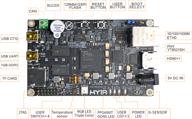
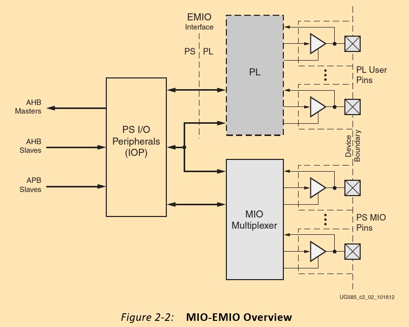
Those, are connected either to the PL or the PS part of a Zynq.
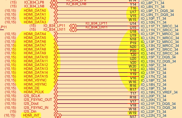
In order to find, where the HDMI is connected to, we can reference the schematics.
According to these, they are connected to the PL part (since the PS pins are numbered as MIO_#).
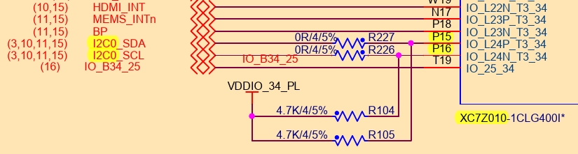
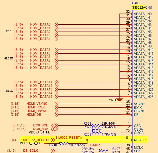
Looking further down [the schematics], we see that the signals pass through an “HDMI transmitter”.
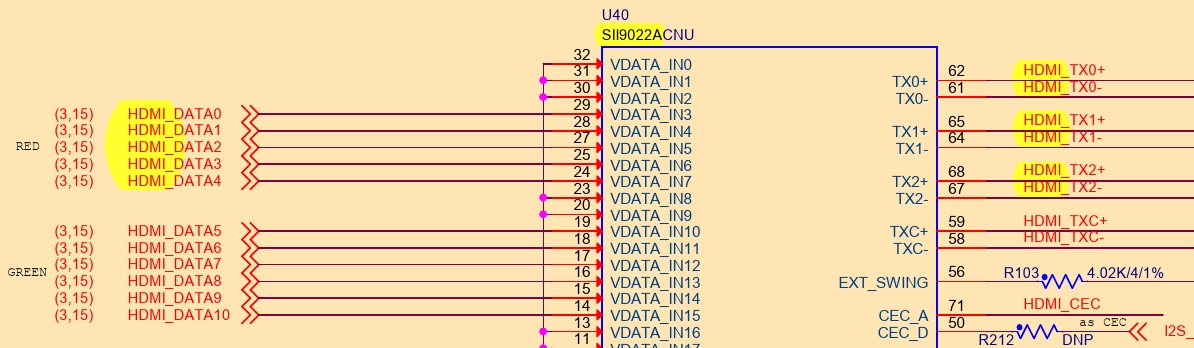
As a result, we have to power up the transmitter. In order to do so, we see that it communicates through the I2C-0 bus, thus we’ll need an I2C interface to do so.
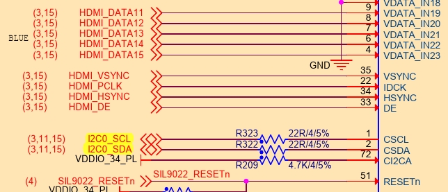
I2C-0 is connected to PL as P15 & P16
Design

A relatively easy method, is to let the PS handle the powering up of the transmitter. The PL will handle the graphics part.
(Another method, would be through .coe files (traffic generator), eliminating the need for the PS).
This design, features an AXI I2C interface (TODO use native) to talk to the common i2c-0 bus (at least three devices use it, though).
A clocking wizard is needed in order to provide a different clock for the pixels. Note: Although Sil9022A may handle up to 165MHz, it features a multiplier (and a divider) if the need arises.
(A constraint file is provided in the constraint files folder). Naming the external, block design, ports according to the constraint file helps with automatic assignment 🙃 (TODO 🙂↔️).
PS - Activating Sil9022A (i.e. the HDMI transmitter)
(TODO move to native/ PS I2C)
The minimal configuration needed is the following:
- Raise the
RESETnsignal [to power up Sil9022A] - Write
0x00to register0xC7, in order to enable the TPI (Transmitter Programming Interface) - Wait for ID to stabilize (at 0x1B-1D, 30).
- Enable source termination (might be unnecessary, depending on the schematic/ external resistors)
- Disable TMDS output (at
0x1A) (default) - Switch from D2 to D0 state (at
0x1E) - Enable TMDS output (at
0x1A)
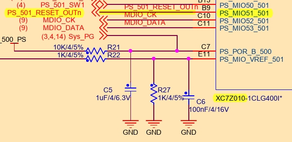
- The RESETn signal will be handled using the Gpio-PS standalone driver
- The i2c will be handled using the AXI-I2C standalone driver
GPIO
Schematics
There are 2 drivers for GPIO, one through AXI and one using the native/ PS MIO?.
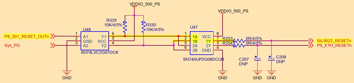
Searching through the schematics for the RESETn pin, we can see it’s connected to MIO51. (The signal passes first through a buffer and then through an AND gate).
Code
The library being used is called Gpio-PS. API.
Gpio is first initialized:
- XGpioPs_LookupConfig() ▶ Retrieves the addresses assigned to the Gpio-PS controller and the related (parent?) interrupts
- XGpioPs_CfgInitialize() ▶ Sets the XGpioPs instance’s variables.
Next the pins are set:
- XGpioPs_SetDirectionPin() ▶ Which sets the pin as input/output
- XGpioPs_SetOutputEnablePin()
And written:
- XGpioPs_WritePin()
I2C
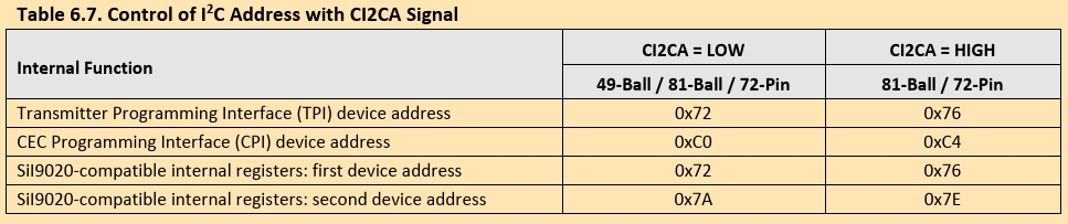
It’s important to note that the address is 0x3B. This derives from 0x76 » 1, which means that the datasheet depicts the 8-bit versions.
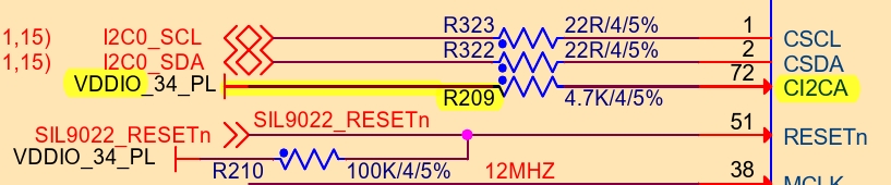
Needless to say, CI2CA has been raised (assuming R209 is in place).
Code
The driver used is called AXI-I2C. API.
Only two functions are used (retained for simplicity):
- XIic_Recv()
- XIic_Send()
These operate using polled I/O and blocks.
It is important, however, that we are the only Master of the bus.
(No interrupts are needed).
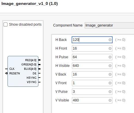
PL - Creating a signal generator
HDMI does not care about Hsync/Vsync polarity, so let’s keep them positive (to reduce Sil9022A configuration).
A sample vhdl file is provided inside the code folder, named Image_generator.vhd:
library ieee;
use ieee.std_logic_1164.all;
use ieee.numeric_std.all;
use ieee.math_real.all; -- Needed for the `ceil()` function

-- ===============================================
--  For synchronisation, pixels are ordered as
--    Visible, Front, H/V Pulse, Back, [-repeat-]
-- ===============================================
entity Image_generator is
    Generic (
        -- ===============================
        --  Horizontal timing (in pixels)
        -- ===============================
        H_VISIBLE   : natural := 640;
        H_FRONT     : natural := 16;
        H_PULSE     : natural := 64;
        H_BACK      : natural := 120;

        -- =============================
        --  Vertical timing (in pixels)
        -- =============================
        V_VISIBLE   : natural := 480;
        V_FRONT     : natural := 1;
        V_PULSE     : natural := 3;
        V_BACK      : natural := 16);

    Port (
        CLK     : in  std_logic;
        RESETN  : in  std_logic;

        -- ========
        --  Colors
        -- ========
        RED     : out std_logic_vector(4 downto 0);
        GREEN   : out std_logic_vector(5 downto 0);
        BLUE    : out std_logic_vector(4 downto 0);

        -- =======================================
        --  Data Enable (signals visible pixels)
        --  Unrelated to VGA. Required by HDMI.
        --  The HDMI transmitter can generate it.
        -- =======================================
        DE      : out std_logic;

        -- =======================================================
        --  Synchronization signals (polarization is unnecessary)
        -- =======================================================
        HSYNC   : out std_logic;
        VSYNC   : out std_logic);
end Image_generator;

architecture arch of Image_generator is
    -- ====================================
    --  Calculate required bits for number
    -- ====================================
    function bit_width (num: natural) return natural is
    begin
        if num = 0 then
            return 1;
        else
            return integer(ceil(log2(real(num + 1))));
        end if;
    end function bit_width;

    -- =========
    --  Aliases
    -- =========
    constant H_TOTAL        : natural := H_VISIBLE + H_FRONT + H_PULSE + H_BACK;
    constant V_TOTAL        : natural := V_VISIBLE + V_FRONT + V_PULSE + V_BACK;
    -- ==
    constant HSYNC_START    : natural := H_VISIBLE + H_FRONT;
    constant HSYNC_STOP     : natural := H_VISIBLE + H_FRONT + H_PULSE - 1;
    -- ==
    constant VSYNC_START    : natural := V_VISIBLE + V_FRONT;
    constant VSYNC_STOP     : natural := V_VISIBLE + V_FRONT + V_PULSE - 1;

    -- ===========
    --  Variables
    -- ===========
    signal h_pos    : natural range 0 to 2**bit_width(H_TOTAL) - 1;
    signal v_pos    : natural range 0 to 2**bit_width(V_TOTAL) - 1;
begin
    HSYNC   <= '1' when
        h_pos >= HSYNC_START and
        h_pos <= HSYNC_STOP else '0';
    VSYNC   <= '1' when
        v_pos >= VSYNC_START and
        v_pos <= VSYNC_STOP else '0';

    -- ===============================================
    --  (Pixel ordering: Visible, Front, Pulse, Back)
    -- ===============================================
    DE      <= '1' when h_pos < H_VISIBLE and v_pos < V_VISIBLE else '0';

    -- ========
    --  Output
    -- ========
    RED     <= std_logic_vector(to_unsigned(16#19#, RED'length));
    GREEN   <= std_logic_vector(to_unsigned(16#19#, GREEN'length));
    BLUE    <= std_logic_vector(to_unsigned(16#70#, BLUE'length));

    -- ================
    --  Advance line
    --  Advance column
    -- ================
    process (CLK, RESETN) is
    begin
        if rising_edge(CLK) then
            -- =======
            --  Reset
            -- =======
            if RESETN = '0' then
                h_pos   <= 0;
                v_pos   <= 0;
            else
                if h_pos >= H_TOTAL - 1 then
                    h_pos   <= 0;
                    -- ===============
                    --  Restart frame
                    -- ===============
                    if v_pos >= V_TOTAL - 1 then
                        v_pos   <= 0;
                    -- ======================
                    --  Advance to next line
                    -- ======================
                    else
                        v_pos   <= v_pos + 1;
                    end if;
                -- ========================
                --  Advance to next column
                -- ========================
                else
                    h_pos   <= h_pos + 1;
                end if;
            end if;
        end if;
    end process;
end arch;
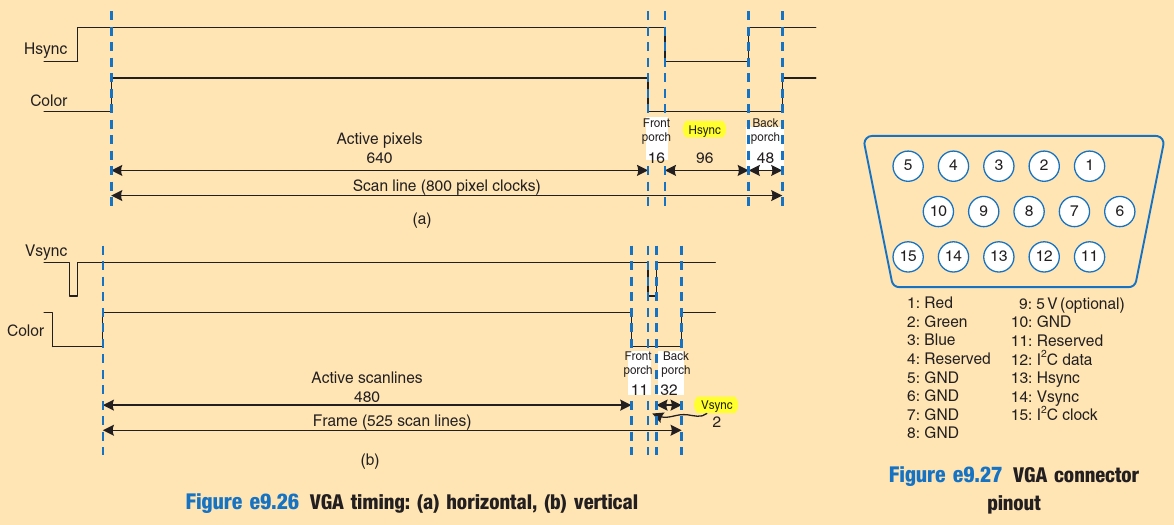
What we need, is values for Front/Back porches and H/V sync pulses, for each monitor we are going to connect to. (Although remnant from CRTs, they are probably needed for modern, digital, displays).
Monitor capabilities
One way to read the monitor’s capabilities, is through its edid file.
- One way to access it under linux, is via the
/sysinterface usingedid-decode: $ edid-decode /sys/devices/pci0000\:00/0000\:00\:02.0/drm/card0/card0-HDMI-A-1/edid- ^ The proper path can be searched:
$ find /sys -name edid
Example edid files are included in the edids folder.
edid-decode (hex):

00 ff ff ff ff ff ff 00 4c 2d d0 01 31 32 52 42
04 10 01 03 80 2b 20 78 2a ee 95 a3 54 4c 99 26
0f 50 54 bf ef 80 a9 40 81 80 81 40 71 4f 01 01
01 01 01 01 01 01 48 3f 40 30 62 b0 32 40 40 c0
13 00 b0 44 11 00 00 1e 00 00 00 fd 00 38 4b 1e
51 11 00 0a 20 20 20 20 20 20 00 00 00 fc 00 53
79 6e 63 4d 61 73 74 65 72 0a 20 20 00 00 00 ff
00 48 53 58 41 31 30 33 31 35 32 0a 20 20 00 f4

----------------

Block 0, Base EDID:
  EDID Structure Version & Revision: 1.3
  Vendor & Product Identification:
    Manufacturer: SAM
    Model: 464
    Serial Number: 1112683057
    Made in: week 4 of 2006
  Basic Display Parameters & Features:
    Digital display
    Maximum image size: 43 cm x 32 cm
    Gamma: 2.20
    DPMS levels: Off
    RGB color display
    First detailed timing is the preferred timing
  Color Characteristics:
    Red  : 0.6396, 0.3300
    Green: 0.2998, 0.5996
    Blue : 0.1503, 0.0595
    White: 0.3134, 0.3291
  Established Timings I & II:
    IBM     :   720x400    70.081663 Hz   9:5     31.467 kHz     28.320000 MHz
    DMT 0x04:   640x480    59.940476 Hz   4:3     31.469 kHz     25.175000 MHz
    Apple   :   640x480    66.666667 Hz   4:3     35.000 kHz     30.240000 MHz
    DMT 0x05:   640x480    72.808802 Hz   4:3     37.861 kHz     31.500000 MHz
    DMT 0x06:   640x480    75.000000 Hz   4:3     37.500 kHz     31.500000 MHz
    DMT 0x08:   800x600    56.250000 Hz   4:3     35.156 kHz     36.000000 MHz
    DMT 0x09:   800x600    60.316541 Hz   4:3     37.879 kHz     40.000000 MHz
    DMT 0x0a:   800x600    72.187572 Hz   4:3     48.077 kHz     50.000000 MHz
    DMT 0x0b:   800x600    75.000000 Hz   4:3     46.875 kHz     49.500000 MHz
    Apple   :   832x624    74.551266 Hz   4:3     49.726 kHz     57.284000 MHz
    DMT 0x10:  1024x768    60.003840 Hz   4:3     48.363 kHz     65.000000 MHz
    DMT 0x11:  1024x768    70.069359 Hz   4:3     56.476 kHz     75.000000 MHz
    DMT 0x12:  1024x768    75.028582 Hz   4:3     60.023 kHz     78.750000 MHz
    DMT 0x24:  1280x1024   75.024675 Hz   5:4     79.976 kHz    135.000000 MHz
    Apple   :  1152x870    75.061550 Hz 192:145   68.681 kHz    100.000000 MHz
  Standard Timings:
    DMT 0x33:  1600x1200   60.000000 Hz   4:3     75.000 kHz    162.000000 MHz
    DMT 0x23:  1280x1024   60.019740 Hz   5:4     63.981 kHz    108.000000 MHz
    DMT 0x20:  1280x960    60.000000 Hz   4:3     60.000 kHz    108.000000 MHz
    DMT 0x15:  1152x864    75.000000 Hz   4:3     67.500 kHz    108.000000 MHz
  Detailed Timing Descriptors:
    DTD 1:  1600x1200   60.000000 Hz   4:3     75.000 kHz    162.000000 MHz (432 mm x 324 mm)
                 Hfront   64 Hsync 192 Hback  304 Hpol P
                 Vfront    1 Vsync   3 Vback   46 Vpol P
    Display Range Limits:
      Monitor ranges (GTF): 56-75 Hz V, 30-81 kHz H, max dotclock 170 MHz
    Display Product Name: 'SyncMaster'
    Display Product Serial Number: 'HSXA103152'
Checksum: 0xf4
After identifying a proper mode, say.. DMT 0x06, we can ask tinyvga.com for the proper timings 😇. (TODO failed @ LG Flatron L2000C), and set them as generics:
Maximum resolution can be achieved with the settings under Detailed Timing Descriptors [in the edid file].